
Electromagnetic status indicators are ideal for applications which require great visibility in difficult light conditions and built-in memory which allows to display critical information after all power is gone. Typical applications include transient recorders, industrial process displays, portable field measuring equipment displays, contact status indicators and any binary on / off indicators.
Operating characteristics
Each disk contains a permanent magnet which interacts with an electromagnet. A current pulse activates a reversal of the magnetic field induced in the electromagnet which determines whether the segment is exposed (set) or retracted (reset). Indicators are available in many different styles and sizes, in a range of fluorescent colors including green, yellow, red and orange, in addition to white. For a complete listing refer to our color chart, available on request.
Visibility
The light reflecting, rotating fluorescent disks in these indicators provide excellent visibility in most ambient light conditions.
Reliability
The disks are the only moving parts and are rated at the minimum of 100 milion operations the indicators are extremely rugged and ideal for use in applications over a wide range of environmental conditions. Magnetic memory retains the indicators’ status through shock, vibration or power failure making them ideal for mobile applications.
Economy
Power is only required to change the data displayed. Inherent magnetic memory in each segment retains the display indefinitely without power being applied. Multiple displays can be operated on a few watts of total power.
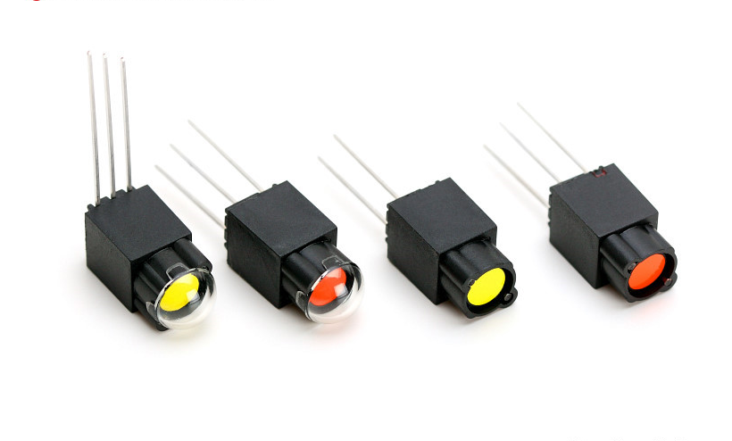
Available types
| disk size | C | R / F | P | model | ND / NR | example | |
|---|---|---|---|---|---|---|---|
| status indicator series 30: | 7,0mm | + | + / + | + | 30 | + / + | C30NR |
C – cap, R – right angle pins, F – full angle pins, P – mount plate, ND – 3 pins, NR – 2 pins
Attention: Not all combinations are possible. The mount plate is designed only for F version of the pins. This indicator is supposed to be installed in a cutout in a PCB and the pins must go around it to return to the PCB t be soldered at the edge of the cutout.
Available colors
01 – white, 02 – orange, 03 – green, 05 – red, 06 – yellow. All other colors upon request.
Technical data
| series: | 30 |
|---|---|
| overal size: | 11.5mm x 11.5mm 0.45" x 0.45" |
| disk size: | 7mm 0.30" |
| weight: | 4.5g 0.16oz |
| current pulse: | 1,5ms |
| min. amplitude: | 250mA |
| min. voltage: | 4,5V |
| max. voltage: | 125V |
| coil resistance: (at 20°C ambient) | 12Ω ±10% |
| max. coil temperature: | 95°C |
| power to maintain displayed data: | ZERO |
| temperature range: | -40°C to 92°C -40°F to 196°F |
| relative humidity: | up to 95% (provided no condensation occurs) |
| outdoor application: | requires a weatherproof enclosure |
Electrical characteristics
All indicators are current operated devices. Applied voltages must be sufficient to develop minimum specified current over full operating temperature range. Drive pulse duration requirements include current rise time. Coil drive requirements are specified at the module input terminals.
![]()
![]()